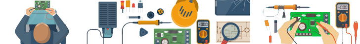
Introduction:
These days, time is money, and we all need to find the quickest way to get what we need, be it a product, a service, or an outcome. One way to save time on projects is to use a ‘development board’. Development boards help save up time consumed in the basic setup of your projects.
What is a development board?
Contents
- 1 What is a development board?
- 2 Components of a Development Board:
- 3 ZERO-IoT-Development Board – ZID-2020-V1.0:
- 4 PCB Package Unboxing of ElectronicsLovers ZERO-IoT-Development Board video
- 5 ElectronicsLovers ZERO-IoT-Development Board V1.0 Video
- 6 Components of the ZERO-IoT-Development Board
- 7 Uploading Gerber File and Order at JLCPCB Website:
- 8 ElectronicsLovers ZERO-IoT-Development Board – ZID-2020 Assembling:
- 9 ZID-2020 PICTURE Gallery :
- 10
- 11 Related
A development board is simply a printed circuit board which comes with pre-installed circuitry and hardware. These boards help to save time when you are repeatedly working on a type of microcontroller. And so, instead of setting up the circuitry and hardware on a breadboard every time you simply work with a development board that comes with everything set up beforehand. This is particularly useful if you’re using a microcontroller for general repetitive experimentation and prototyping. 
There is also the chance of errors if you’re building a basic setup yourself every time with a breadboard since you could mess up the connections, and so in the case of errors in your project, it is difficult to identify if the error is due to your setup or the programming. And so, debugging will consume even more time. This is why it is better to use a development board, plus you can use development boards in multiple projects, it is a one-time investment that surely pays off.
Components of a Development Board:
The basic components found in a development board include:
- A power circuit, usually set to work on a 9V power supply
- A programming interface used to program the microcontroller via your computer
- Basic input (for e.g. buttons)
- Basic output (for e.g. LEDs)
- Input/Output pins (I/O pins)
ZERO-IoT-Development Board – ZID-2020-V1.0:
Electronicslovers recently designed a New Development Board version 1.0 called “ZERO-IOT-DEVELOPMENT BOARD” for Students and Tech Lovers, it has based on the Internet of things (IoT).

You can use ZID-2020 to make projects related to automation, security, and all types of smart home applications. JLCPCB has sponsored all the electronic components and the PCBs for this development board.

Good luck! You can create multiple projects by using our new development board. The IoT domain is ever-increasing in popularity and demand. With development boards, you will find ease in your capability to create new projects. What projects are you most interested in making first?
PCB Package Unboxing of ElectronicsLovers ZERO-IoT-Development Board video
ElectronicsLovers ZERO-IoT-Development Board V1.0 Video
ElectronicsLovers ZERO-IoT-Development Board V2.0 3D view (UPDATED on August 2020)
In ZID-2020-V2.0 Board we changed the Power Supply unit and we replaced the Traditional LM7805 with HLK-PM01 AC-DC which is more efficient and reliable. We Fixed The Relays issue in our development board.

Components of the ZERO-IoT-Development Board
The ZERO-IoT-Development Board is built using high-quality components. We’ll be going over them briefly.
- ESP8266 NodeMCU x 1:
Internet Of Things is trending in the world of tech and it has influenced the way we work, particularly in the form of smart home technology and automation. Espressif Systems, located in Shanghai, kept this in mind when they created the ESP8266. The ESP8266 NodeMCU is a small Wi-Fi enabled microcontroller. And what’s truly remarkable is its pricing, a mere $3! It is perfect for projects. It comes in a compact design and designed particularly for IoT applications, mobile devices, and wearable electronics. It can connect and control devices from anywhere around the world. 
The NodeMCU (Node Microcontroller Unit) is basically an open-source software that is built around the ESP8266. It assists you in building/prototyping IoT projects and electronics.
- MCU (Microcontroller Unit)
A microcontroller unit is a small computer on a single metal-oxide-semiconductor chip. It contains one or more processing units and programmable I//O peripherals. They are embedded in devices to help control the actions of the product. They are used in automated automobiles, implants in medical devices, remote controls, toys, all sorts of gadgets, and home appliances,
- Power Pins:
The ESP8266 comes with four power pins, one Vin pin, and three 3.3 V pins. The Vin pin acts as the external power supply and provides 5V, and the 3.3V power pins are supplied 3.3V to power the board. These overall power pins are used to supply power to the external components.
- GPIO Pins:
The ESP8266 comes with 17 GPIO pins (General Purpose Input/Output pins) They can be assigned various functions. Some are not recommended to use whereas others have specific functions such a 12C, 12S, SPI, IR Remote Control, LED light etc. Each GPIO can be configured to internal pull-up or pull-down, or you can set them to high impedance. You can also generate CPU interrupts by configuring as inputs. 
- OLED Display x 1:
ZERO-IoT-Development Board is compatible with the OLED display model SSD1306. The SSD1306 is a 128×64 dot single chip driver that is used for graphic display systems It is integrated into OLED display modules. This one, in particular, is a mono-colour, 0.96-inch display that comes with four pins. ![]()
The OLED display is made up of 128×64 individual pixels and each individual pixel can be turned on or off via the controller chip, the display makes its own light and so the backlight is not required in this type of display. Although the display is small it is highly readable because of the OLED’s high contrast.
The SSD1306 model is connected to the ESP8266 through an I2C communication protocol.
Specifications:
- SSD1306 chip
- 128×64 resolution, monochrome, 7-pins, 0.96” display
- I2C communication protocol
- 160° viewing angle
- 3V-5V DC supply voltage
- -30°C – 70°C (temperature range)
- Dimensions: 27.0mm x 27.0mm x 4.1mm (without headers)
You can make multiple OLED display projects by using our ZID-2020 Board.
- Motion Sensor x 1:
The ZID-2020 development board is compatible with the PIR Sensor (HC-SR501 DYP-ME003) which will detect motion within its range. A PIR sensor usually has a range of 5m-12m. They are small in size, pocket-friendly, low-power and easy to use, plus they don’t wear out easily. This is why they are commonly found in appliances and gadgets. They are known as “Passive Infrared”, “Pyroelectric”, and “IR motion” sensors. They can detect infrared radiation. 
PIR motion sensors are used in switches, security systems, automatic lighting automation and industrial automation systems.
- Temperature and Humidity Sensor x 1:
The ZID-2020 board is compatible with the DHT22 sensor. The DHT22 is a basic, low-cost, digital-output relative humidity and temperature sensor. It uses a capacitive humidity sensor along with a thermistor to measure the surrounding air and gives a reading in the form of a digital signal on the data pin. 
It can measure temperature in the range of -40 to +125 degrees Celsius with +-0.5 degrees accuracy and can measure humidity in the range of 0-100% with 2-5% accuracy.
- Gas Leakage sensor x 1:
The ZID-2020 board is also compatible with the MQ gas and pollution detector series. These sensors are widely used because of their ability to detect various kinds of gases, aerosols and smoke/ash particles. These sensors are actually metal-oxide semi-conductor gas sensors or ‘chemiresistors’ which change resistance when they come in contact with a gas. A simple voltage divider network can be used to detect concentrations of gas. This sensor can detect gases such as ethanol, propane, methane, CO, hydrogen, flammable gases etc. 
- Flame Sensor x 1:
Next, the board is compatible with the LM393 flame sensor, or more accurately the infrared flame sensor module, it can detect a flame or light source of the wavelength ranging from 760nm-1100nm. You can connect the small plate output interface and chip directly to the microcomputer I/O port. 
In order to prevent damage due to high temperature, the sensor should be placed at a reasonable distance from the flame. The shorted distance it should be at is 80cm, for larger flames test it from a greater distance. This flame sensor is used in fire alarms and fire detecting devices.
- Relay x 3:
The board makes use of the SRA-05VDC-CL 5V relay, a very well-known relay for electronic hobbyists. The relay comes with two outputs i.e. NO (normally open) and NC (normally closed). When you connect the IN1 or IN2 pin to the ground, NO will open and NC will subsequently close. Similarly, when IN1 or the IN2 pin is not connected to the ground, NO will close and NC will open.

You can connect a circuit or device between these two pins the common pin on output, and a power source will let you toggle power to a circuit/device.
Relays are commonly used in switching circuits, in-home automation projects, in the control of heavy loads, in safety circuits to cut off the load from the supply in the case of emergency, and in automobiles.
- Voltage Regulator x 1 – Not using Anymore in Version 2.0
Voltage regulators are systems designed to maintain a particular voltage level. They are commonly found in electronic circuits. In this particular ZID-2020 development board, we used the 7805 IC voltage regulator. The name gives you an idea of its specifications. ‘78’ means that it is a positive voltage regulator whereas ‘05’ means that it provides 5V as output. SO the output will be +5V
The output current of this IC can go up to 1.5A high but we recommend a heat sink for projects that will consume higher current.
ZID-2020-V2.0 Board we changed the Power Supply unit and we replaced Traditional LM7805 with HLK-PM01 AC-DC which is more efficient and reliable.

ZID-2020-V2.0 Board Components used:
- ESP8266 NodeMCU X 1
- HLK-PM01 AC-DC X 1
- OLED Display I2C 0.96-inch X 1
- Motion Sensor – HC-SR501 or DYP-ME003 x 1
- Temperature and Humidity Sensor DHT22 X 1
- Gas Leakage Sensor MQ2 x 1
- LM393 Flame Sensor x 1
- Transistors x 3
- Diode, Resistors and LEDs
- USB A and USB Micro for 5V input
- 12Vdc Jack in For 12v input
- Slide Switch
LCSC has sponsored all the electronic components for ZID Board-2020
JLCPCB also has its counterpart, LCSC, which is more focused around the distribution of electronic components. Located in Shenzhen and founded in 2011, now catering to over 900,000 customers worldwide. It has a wide range of products for you to choose from including semiconductors, resistors, capacitors, diodes, inductors, connectors, transistors and sensors etc.
The company itself is ISO 9001: 2015 certified. It ships worldwide and offers multiple shipping methods including DHL, FedEx, EMS and Airmail. Check out their website for more insight https://lcsc.com.
Uploading Gerber File and Order at JLCPCB Website:
JLCPCB aka JiaLiChuang Co., Limited based in Hong Kong is a PCB manufacturing company that deals in high-quality PCB prototypes and small-batch PCBs at an extremely cost-effective rate. They have been working in this field for over 14 years and now claim to have over 800,000 customers worldwide.
They provide 1-layer, 2-layer and multi-layer PCBs on-demand and aim to deliver as soon as possible. They offer multiple shipping methods for you to choose from (DHL, UPS, PostLink Registered Mail etc.) JLCPCB is ISO 9001:2015, ISO 14001:2015, ISO 9001:2015 and RoHS certified, making it extremely reliable. You can check them out at https://jlcpcb.com.
ElectronicsLovers ZERO-IoT-Development Board – ZID-2020 Assembling:
ZID-2020 PICTURE Gallery :


For Gerber File and PCB Cooperation Contact Us
THIS DESIGN AND PROJECT IS “”© COPYRIGHTED “” BY ELECTRONICSLOVERS – Do not Sell or Share without the Authorization of Electronicslovers.
1 comment
I am also a Electronics Lover. This article help me to gather more information on electronics,thanks alot.